Honduino OBD2 DPFI - V4
![]()
The Honduino OBD2 DPFI is an aftermarket engine control unit (ECU) designed specifically for Honda vehicles with DPFI (Dual Point Fuel Injection) systems. This guide walks you through the complete setup, calibration, and advanced configuration of the V4 version of this ECU.
This documentation covers:
- Initial setup and installation of required software
- Basic ECU configuration:
- Trigger wheel settings
- Ignition systems
- Injection parameters
- Connecting and calibrating the ECU with your vehicle
- Advanced features including:
- Wideband O2 sensing
- Launch control
- Boost control
- Programmable outputs (CEL, shift lights)
- Reference pinout diagrams for connecting inputs and outputs
Whether you’re upgrading from the stock ECU or replacing an existing aftermarket unit, this guide provides detailed instructions to achieve optimal performance with your Honduino OBD2 DPFI V4.
Before Connecting the ECU to the Car
Download and Install
- TunerStudio software: Download TunerStudio Software
- USB driver: Download USB Driver
Connectivity:
- Bluetooth: Connect via USB to power the ECU and pair the Bluetooth
- USB: Unplug the Bluetooth module and connect via the USB
Create a Project and Detect Firmware
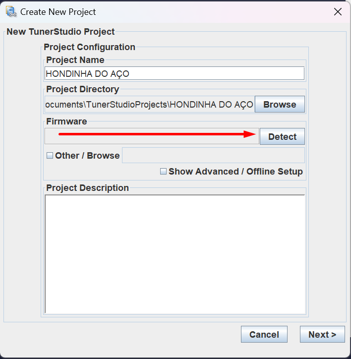

Use controller settings to load ECU settings.
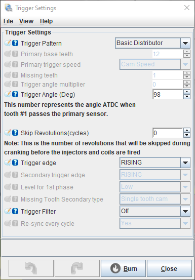
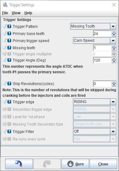
Trigger Wheel
Configure the trigger wheel:


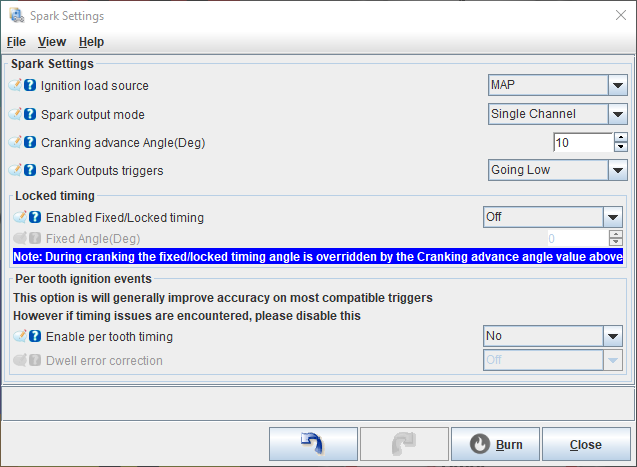
Ignition
On the board Jumper JP1, select the voltage sent to the coils:
- Honda distributor coil: 12V
- VAG / K20 coils: 5V
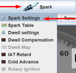

Spark Output Mode:
- Single channel: Distributor
- Sequential: Coil-on-plug
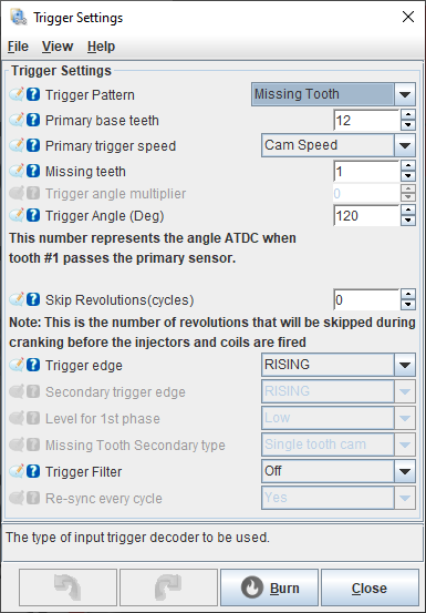
If you want to convert to a coil-on-plug system, you need to change the distributor disc to: Distributor Disc for Honda DPFI.
And configure the trigger wheel pattern to be the same as your disc pattern.
And connect each coil signal to the respective pin declared in the ECU pinout topic.
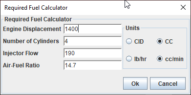
Injection
WARNING: Use only high impedance injectors (> 8 ohm) or low impedance with resistor box.


Change the engine displacement and injector flow rate.
Connecting and Calibrating the ECU
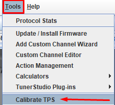
Calibrate TPS
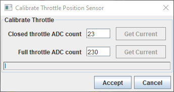
Click on the closed throttle “Get current” button.
Then press full throttle and click on the full throttle “Get current” button.
Now, click “Accept” to save.
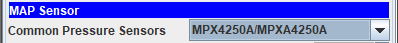
Calibrate MAP
STOCK = Sensor in the engine bay
MPX = Map sensor on the board
Stock map sensor configurations:

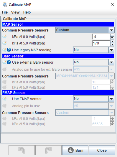
If it uses a map sensor on the board:
MPX42050AP
MPX5700AP

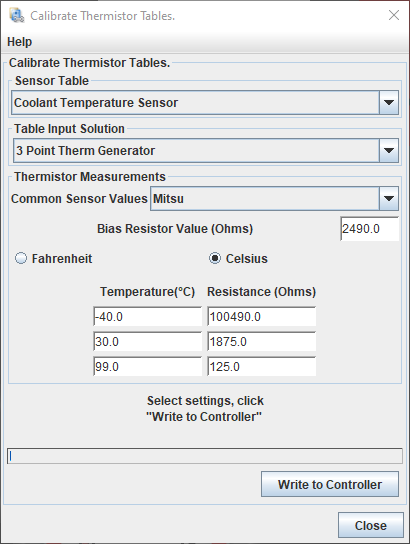
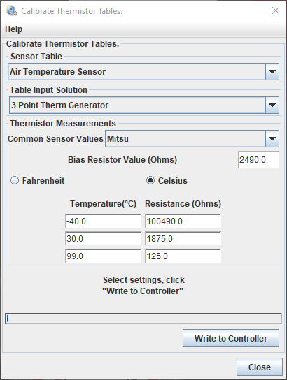
Calibrate Temperature Sensors


Electric Fan
You can control the electric fan by connecting the OBD1 A8 terminal from the ECU to the negative terminal of the fan relay coil.

Base Timing
To sync the ignition timing with the engine, it’s necessary to adjust with the help of a Timing Light Gun for Ignition Calibration.
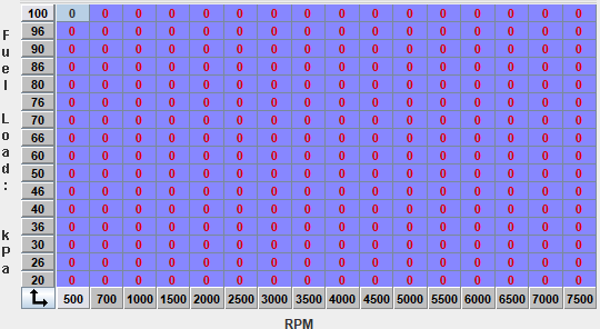
Export the VE table (for later importing).

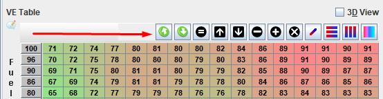
Zero the entire table or disconnect the injectors so that it doesn’t inject fuel while cranking.
Lock the timing.

On the crank, there are 4 marks: 18, 16, 14 and 0 degrees.
The lone mark is 0 degrees. Mark it with a white highlighter.
Put the timing light clamp on spark plug wire number 1 (with the arrow pointing towards the spark plug).
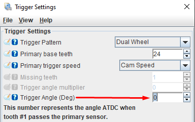
Crank the engine and check if you can see the 0-degree mark.
If not, adjust the trigger angle settings by 30º at a time until you see it.
Then make fine adjustments until the crank mark aligns with the distribution cover mark.
After synchronizing the base timing, import the VE table or reconnect the injectors.

Now, unlock the timing and add 5 to 10 degrees for cranking.
Now, start your car 🎉🎉🎉
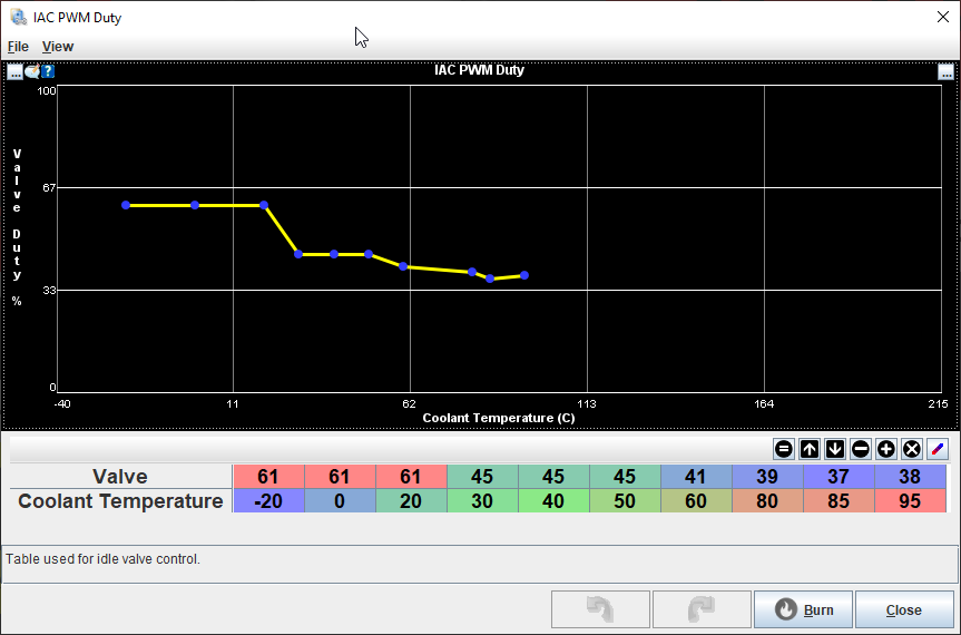
Idle Control

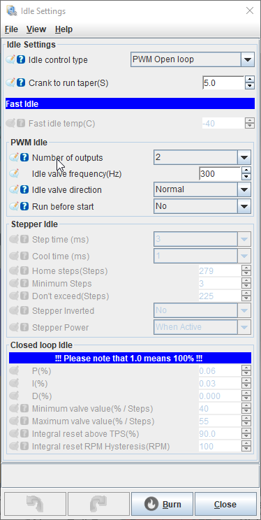
Adjust the duty cycle when the engine is running.
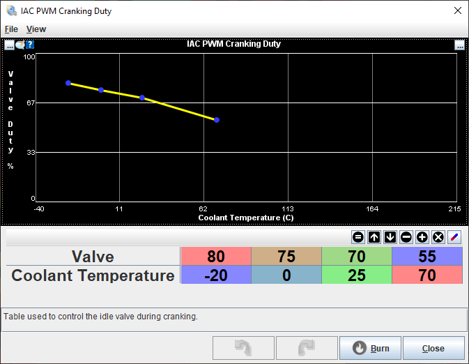
Adjust the duty cycle while cranking.

Advanced Features and Configurations
Wideband
Connect the 0-5V analog wire from the wideband controller to OBD1 D18 or the stock narrow band connector.
Activate the wideband:


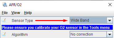
Calibrate the sensor settings:


Choose your wideband from the list.
If it’s not listed, choose “Custom Linear WB” and set the wideband controller values.
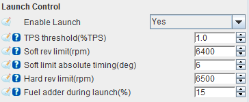
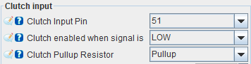
Launch Control
Some cars have clutch switches, but most need to be wired to a switch that sends ground to pin OBD1 B7 when the clutch is pressed.


Boost Control
Connect the negative wire of the MAC Electronic Boost Controller Valve to pin OBD1 B11.
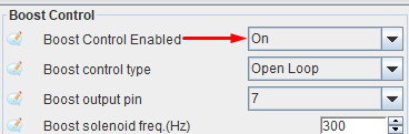
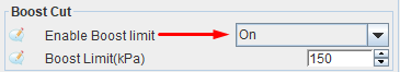
PROTECTION: Enable boost cut when the set value is reached.
Configure the table:


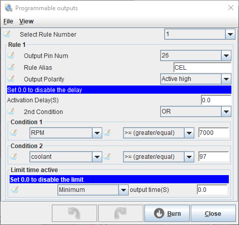
CEL / Shift Light / Temp Light
You can use the engine light as a shift light or as desired through a programmable output.


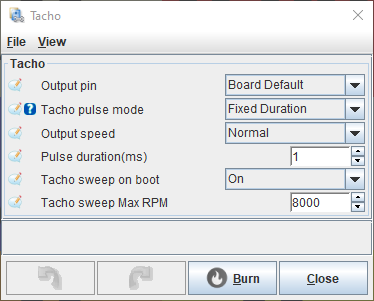
Tachometer
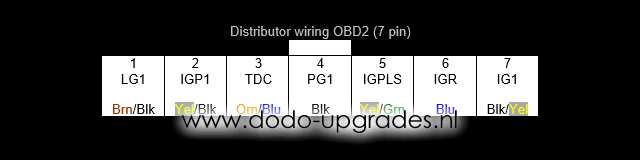
The tachometer is controlled by the distributor. When converting to a coil-on-plug system, you need to activate the TACH jumper on the PCB.
If you want to use the TACH output with the distributor, that’s possible!
Just remove the distributor wire IGR and activate the TACH jumper.
This way, you can have the tacho sweep on boot while maintaining the stock distributor.
Activate tacho output and tacho sweep effect on boot:
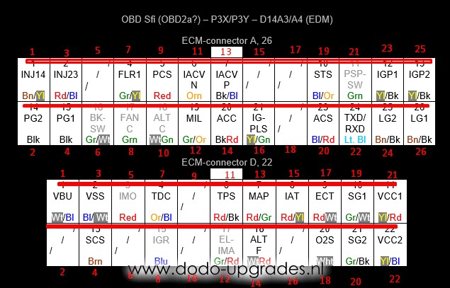
Reference
ECU Pinout
| INPUTS | ECU terminal | Tunerstudio pin |
|---|---|---|
| Clutch | B7 | D51 |
| Vehicle speed sensor | B10 | D20 |
| FLEX sensor | B12 | D2 |
| Aux analog sensor | B14 | A11 |
| Aux temperature sensor | B15 | A9 |
| Throttle position sensor | D11 | A2 |
| Manifold pressure sensor | D13 | A3 |
| Intake temperature sensor | D15 | A0 |
| Coolant temperature sensor | D17 | A1 |
| Wideband 0-5 input | D18 | A8 |
| OUTPUTS | ECU terminal | Tunerstudio pin |
|---|---|---|
| Injector (signal 1) | A1 | D8 |
| Injector (signal 2) | A3 | D9 |
| Fuel pump relay | A7 | D45 |
| Fan relay | A8 | D47 |
| CEL | A12 | D26 |
| Coil 1 | A16 | D40 |
| Coil 2 | B3 | D50 |
| Coil 3 | B4 | D38 |
| Coil 4 | B6 | D52 |
| VTEC (high side) | B8 | D4 |
| Boost | B11 | D7 |
| Tach | D8 | D49 |