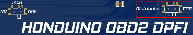
Honduino OBD2 DPFI - V5
![]()
The Honduino OBD2 DPFI is an advanced aftermarket engine control unit (ECU) designed specifically for Honda vehicles with DPFI (Dual Point Fuel Injection) systems. This comprehensive guide covers the complete setup, calibration, and advanced configuration of the V5 version of this ECU.
This documentation covers:
- Pre-installation firmware updates and software setup
- Basic ECU configuration:
- Trigger wheel settings
- Ignition parameters
- Injection configurations
- Vehicle integration and sensor calibration
- Advanced features including:
- Wideband O2 sensing
- Launch control and anti-lag
- Boost control
- Custom output configuration (CEL, shift lights)
- Complete pinout diagrams and connection references
Whether you’re upgrading from a stock ECU, migrating from an older version, or installing a new aftermarket unit, this guide provides detailed instructions to achieve optimal performance with your Honduino OBD2 DPFI V5.
Before connecting the ECU to the car
Before mounting the ECU to the vehicle, some pre-installation configurations should be performed.
Updating the firmware (optional)
Download and install STM32CubeProgrammer V2.14
Download the latest FIRMWARE
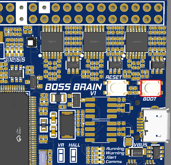
Click on the BOOT button on the board and plug the USB cable into the computer
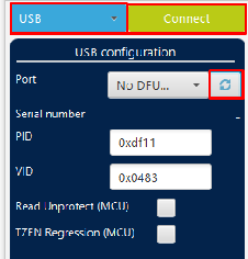
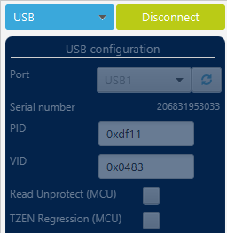
 In STM32CubeProgrammer, select USB, refresh the devices, select the ECU, and connect.
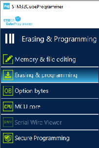
 Go to the “Erasing & programming” menu, browse, and select the firmware.ini file extracted before.
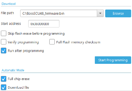 Insert the start address: 0x0800000
Select the boxes: “Run after programming”, “Full chip erase” and “Download file”
Click “Start Programming”
You successfully updated the firmware! Now, close all the STM32CubeProgrammer windows and restart the ECU by clicking the RESET button or unplug and plug the USB cable.
Insert the start address: 0x0800000
Select the boxes: “Run after programming”, “Full chip erase” and “Download file”
Click “Start Programming”
You successfully updated the firmware! Now, close all the STM32CubeProgrammer windows and restart the ECU by clicking the RESET button or unplug and plug the USB cable.
Connecting to the software
Download and install: TunerStudio
Plug the USB, it will automatically open a virtual drive with a file
 Extract it, and save it on your desktop.
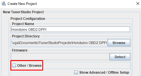
Open TunerStudio, create a new project, click “Other / Browse” and select the firmware.ini file extracted before.
Extract it, and save it on your desktop.
Open TunerStudio, create a new project, click “Other / Browse” and select the firmware.ini file extracted before.
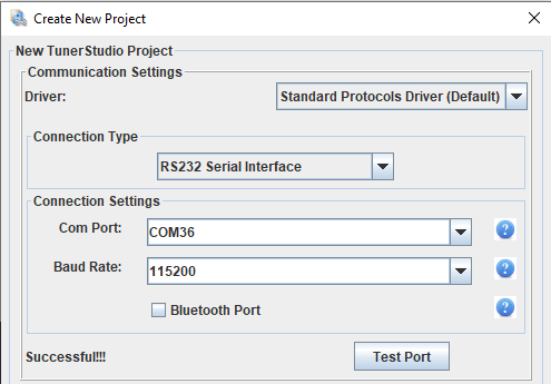
 Use RS232 Serial for USB connection or Bluetooth direct
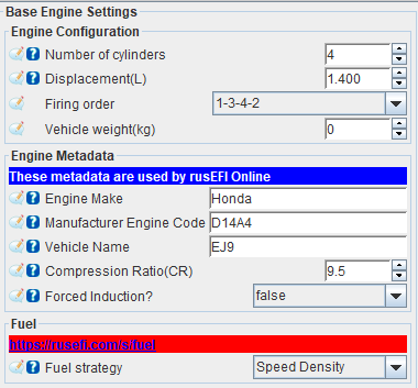
Base settings
Configure the number of cylinders, engine displacement in liters, firing order, and fuel strategy.


Ignition (Distributor / COP)
WARNING: Use only smart coils or dumb coils with external igniters.
The ICM switch needs to be adjusted based on the ignition setup. (CRITICAL)
Configure the Spark Mode and Output Mode
CRITICAL WARNING: If the output mode isn’t configured correctly, the coil(s) will overheat and potentially get damaged. If the ignition is ON and the coil starts to heat up, the configuration is likely incorrect.


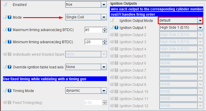
Spark mode:
- Single coil: Distributor
- Individual coils: Smart coils in sequential mode
Ignition output mode:
- Honda distributor DPFI coil: Default (Going Low)
- Most of the smart coils: Default (Going Low)
Ignition voltage output: select the voltage for each pair of ignition output via the jumpers:
H1 + H2 H3 + H4 H5 + H6 H7 + H8 H9 + H10 H11 + H12
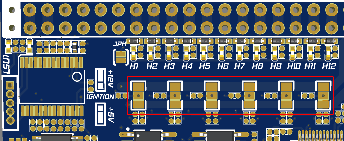
- Honda distributor: 12V
- Most of the smart coils: 5V
If using individual coils: Connect each coil signal wire to the OBD1 C connector.
C5: Coil 1 (High side 1)
C7: Coil 2 (High side 2)
C9: Coil 3 (High side 3)
C11: Coil 4 (High side 4)
WARNING: Be sure to read all sections on ignition so you don’t damage any coils.
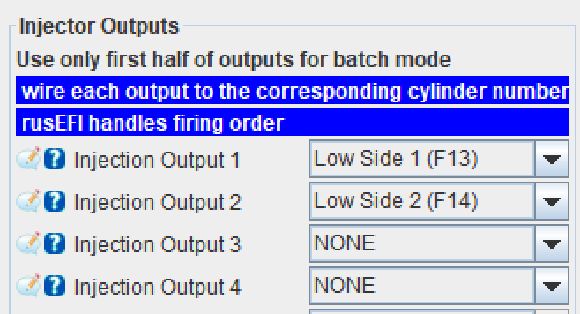
Injection
WARNING: Use only high-impedance injectors (> 8 ohms) or low impedance with a resistor box.
Configure the outputs that correspond to each cylinder.


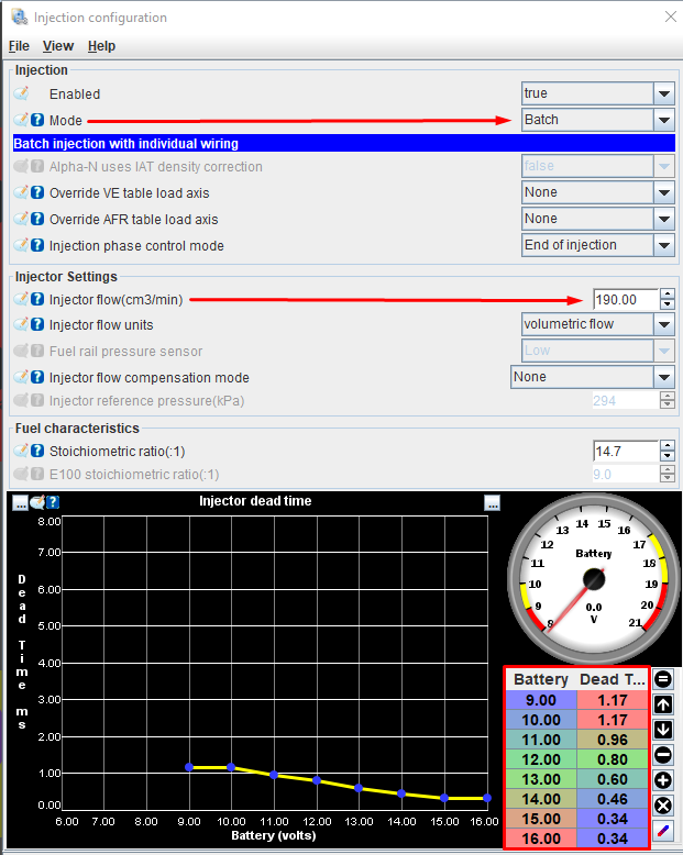
Injector base settings
- Injection mode
- Injector flow
- Compensation mode
- Dead time


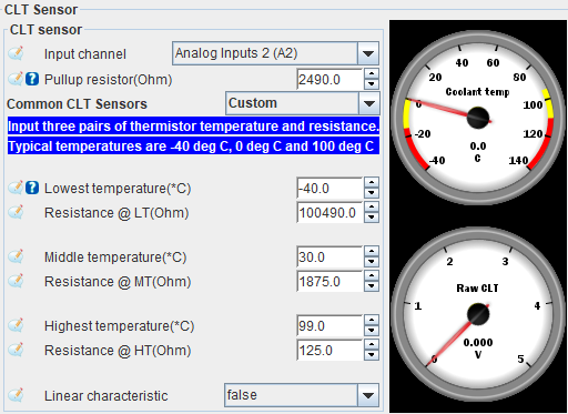
Temperature sensors
Coolant temperature sensor


Intake temperature sensor


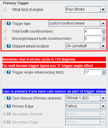
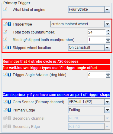
Trigger wheel
Configure the trigger wheel according to your distributor disc:

Stock trigger disc:
24-1 trigger disc:
Connect the ECU to the car
Throttle Position Sensor


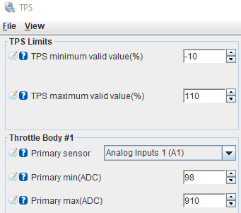
Adjust the Primary minimum (ADC) and Primary max (ADC) until the TPS reads 0% without pressing the throttle and 100% at full throttle.
MAP sensor
Any MAP sensor can be used, but the most used is the stock one on input A4.

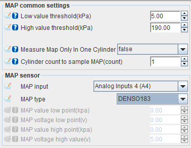
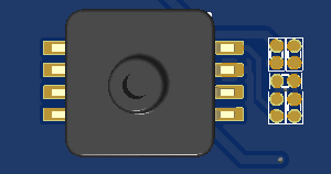
You can also solder an onboard MAP sensor to Analog Input 5 or connect to free analog input.
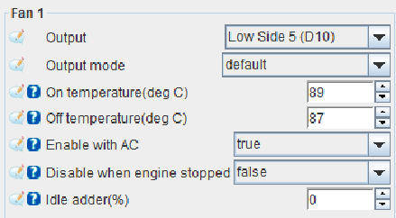
Radiator fan
A valve controls the radiator fan mechanically, but the ECU can activate the relay independently by an unused Low side output.

Ignition base timing (same as the rotation of the distributor)
To sync the ignition timing with the engine, it’s necessary to adjust with the help of a Timing Light gun.
-
Disable the injection (if the car starts, skip this step)


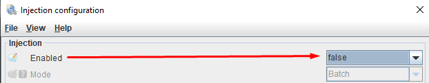
-
Change the timing mode from dynamic to fixed, so the ECU fires the coil always on the 0-degree angle.
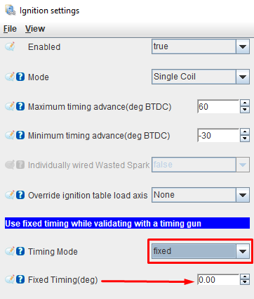
-
Use a white sharpie to mark the 0-degree mark on the crank pulley. The crank pulley has four marks, with the alone mark of the four being 0 degrees (TDC).
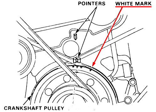
-
Attach the timing light clamp to spark plug wire 1, ensuring the arrow points toward the spark plug.
-
Adjust the Trigger Angle Advance value until the 0-degree mark on the crank pulley aligns with the pointer on the distribution cover.
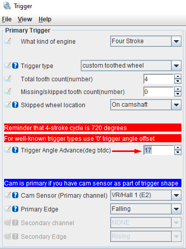
-
Unlock the timing, so the ECU sends the ignition table values.

The timing is synced, now start your car 🥳🥳🥳
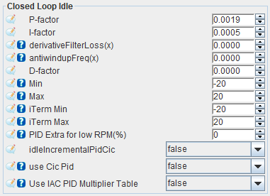
Idle control
Adjust the idle when the engine is at its normal operating temperature.


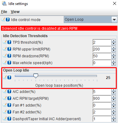
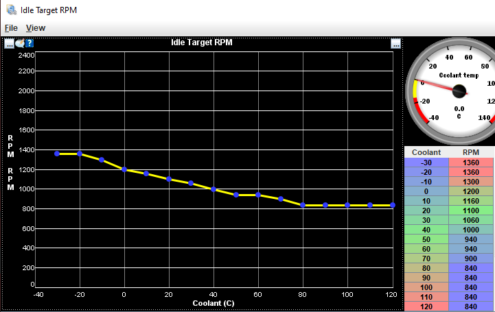
Idle Target RPM is used to control the idle in closed-loop mode.

Warmup Idle Multiplier adjusts the value based on the open-loop idle setting.


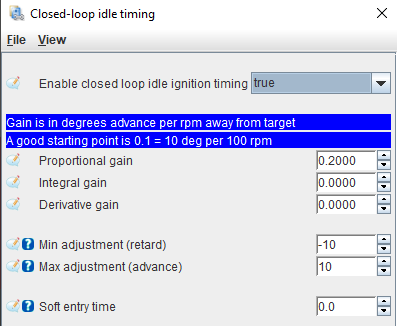
Closed-loop idle adjusts the idle by a PID algorithm.
Closed-loop idle timing adjusts the idle by advancing or retarding the ignition timing.


VTEC solenoid
This engine doesn’t have VTEC solenoid, but you can change to a head with VTEC.


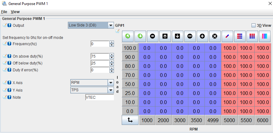
0 = OFF
100 = ON
Vehicle Speed Sensor


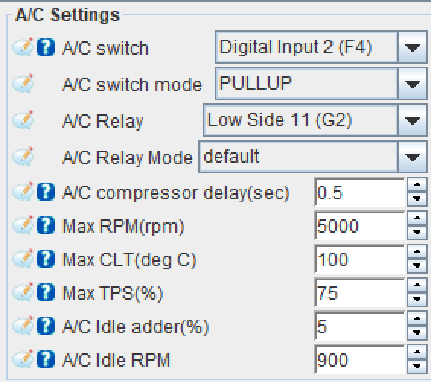
Air Conditioner

Extra features
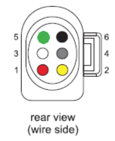
Wideband
To tune the VE table, a wideband sensor for measuring the air-fuel ratio is necessary.
- You can either connect an LSU 4.9 sensor directly to the onboard controller or use a 0-5V signal from an external controller via an auxiliary analog input.
| OBD1 C connector | LSU 4.9 sensor |
|---|---|
| C2 | 5 (IA) |
| C4 | 6 (NERMEST) |
| C6 | 1 (IP) |
| C8 | 2 (VGND) |
| C10 | 3 (HEATER-) |
| C12 | 4 (HEATER+) |
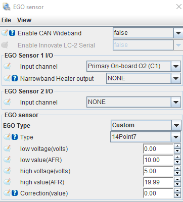
- Configure the wideband linear output values

Launch control
Launch control is used for… I mean, for spitting flames, lots of 🔥🔥🔥!
Select the activation mode: It can be Speed-based, Launch, Clutch, or Brake button.
If you choose to use a button, some cars have clutch switches, but most will need to be wired to a switch that sends a ground signal to pin OBD1 B7 (Aux Digital Input D2) when the clutch is pressed.


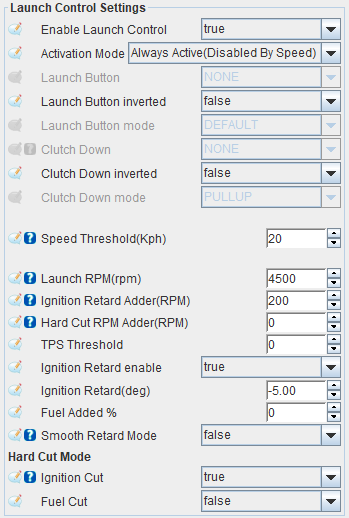
- Launch RPM: A secondary Rev limit engaged by the driver to help launch the vehicle faster.
- Ignition Retard Adder: Range from Launch RPM for Timing Retard to activate.
- Hard Cut RPM Adder: Range from Launch RPM to activate Hard Cut.
- Smooth Retard Mode: Interpolates the Ignition Retard from 0 to 100% within the RPM Range.
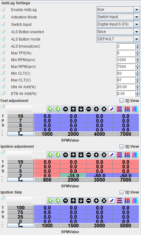
Anti-lag
ANTI-LAG is used to help reduce turbo… I mean, for spitting flames, lots of 🔥🔥🔥!
Wire a switch that sends a ground signal to an unused auxiliary digital input.

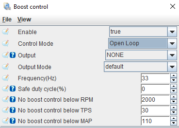
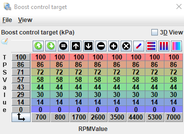
Boost control
A boost controller is a device used to increase the boost pressure produced by the turbocharger.
-
Connect the negative wire of the boost controller valve to an auxiliary low-side output.
-
Activate a boost limit to protect the engine from overboost.


- Boost cut pressure (absolute): MAP value above which fuel is cut in case of overboost.
- Boost cut pressure hysteresis: If hard cut is 160kpa, and boostCutPressureHyst is 10, when the ECU sees 160kpa, fuel/ign will cut, and stay cut until 160-10=150kpa is reached.
- 160kpa absolute = 100 kpa atmosphere + 60 kpa of boost
-
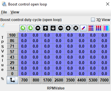
Select Open-loop mode and the auxiliary output. Open-loop: Regulates the boost valve’s duty cycle according to the percentage values in the control table.

-
Configure the Boost control open-loop table.

-
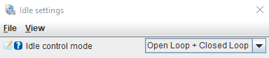
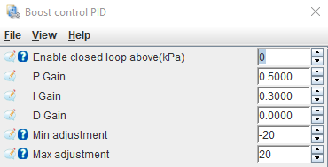
It’s possible to enable the Open + Closed-loop and control the boost more precisely. Open + Closed-loop: Regulates the boost valve’s duty cycle using the open-loop table, combined with a PID algorithm and a target table.

CEL: Shift / Warning light
The engine light can be used as a programmable output. I prefer to use it as a shift indicator and for coolant temperature warnings.

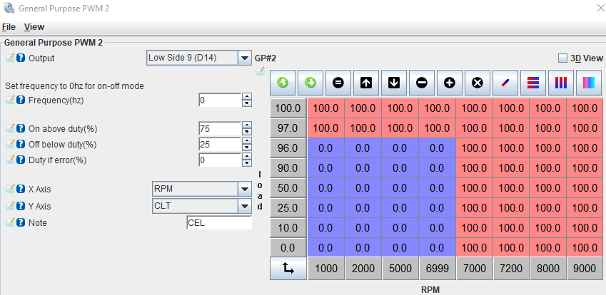
0 = OFF
100 = ON
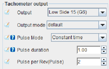
Tachometer
The stock distributor coil sends the RPM signal to the cluster, but the ECU can also control it. When converting to coil-on-plug, the signal from the distributor stops working, so the ECU must provide it.
-
Select the output Low-Side 11 to send the RPM signal.
-
If you’re still using distributor coil and want to control the RPM by the ECU, remove the wire:

-
Select the TACH switch to YES.

Auxiliary inputs/outputs
LOW SIDE: Controls injectors and valves using a ground signal, handling up to 10A.
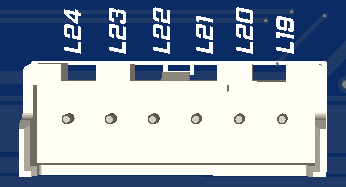
- L19 to L24: Configurable for any auxiliary function
HIGH SIDE: Controls smart ignition coils with 5V or 12V signals.
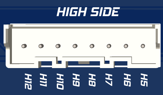
- H5 to H12: Configurable for any auxiliary function
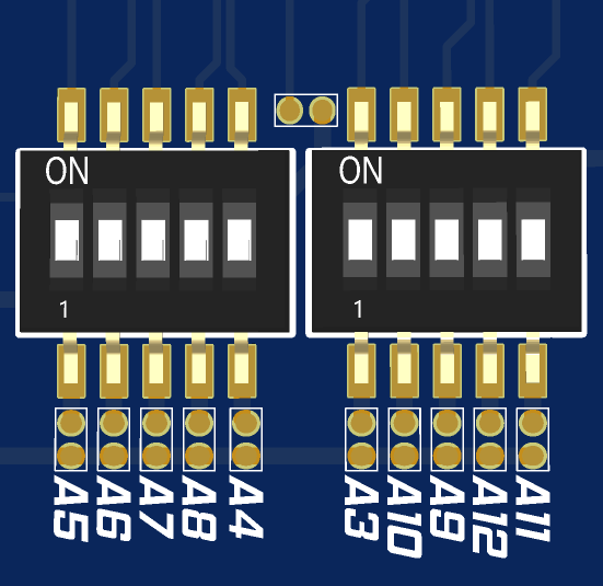
ANALOG: Inputs for sensors with a 0-5V output or for temperature sensors.
| OBD1 B connector | Tunerstudio Analog Input | Function |
|---|---|---|
| B2 | Analog Input 5 | On-board MAP sensor |
| B4 | Analog Input 7 | Free |
| B6 | Analog Input 8 | Free |
| B8 | Analog Input 9 | Knock Input |
| B10 | Analog Input 10 | Free |
| B12 | Analog Input 11 | Free |
| B14 | Analog Input 12 | Free |
NOTE1: If no sensor is wired, it can be repurposed for any other function.
NOTE2: To use temperature sensors, the corresponding input switch must be set to the ON position.
DIGITAL: Inputs for hall sensors (0-5V)
| OBD1 B connector | Tunerstudio Analog Input | Function |
|---|---|---|
| B1 | Digital Input 6 | Free |
| B3 | Digital Input 7 | Free |
| B5 | Digital Input 8 | Free |
NOTE1: If no sensor is wired, it can be repurposed for any other function.
SENSORS: Provides 5V output and ground for powering pressure and temperature sensors.
| OBD1 B connector | Tunerstudio Analog Input | Function |
|---|---|---|
| B7 | +5V | |
| B9 | +5V | |
| B11 | +12V | |
| B13 | Ground | |
| B15 | Ground | |
| B16 | Ground |
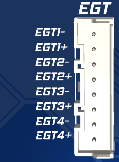
EGT: Inputs for exhaust temperature sensors (Type K)
Drive-by-wire: Controls a 2-wire electronic throttle body or ITB.
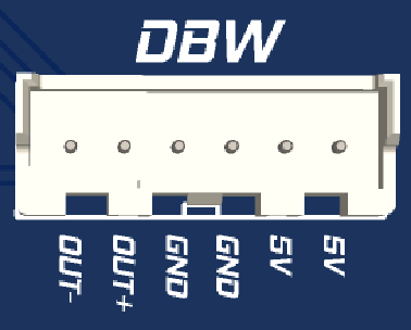
- OUT- & OUT+: Output for ETB motor
- 5V: Power to the potentiometers
- GND: Ground to the potentiometers
NOTE1: If no sensor is wired, it can be repurposed for any other function.
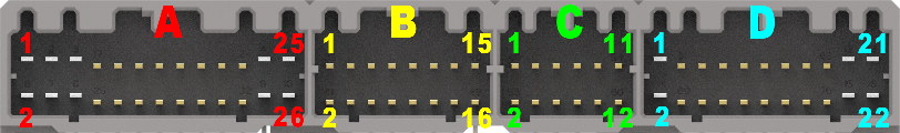
PINOUT: OBD1 DPFI
Connector A
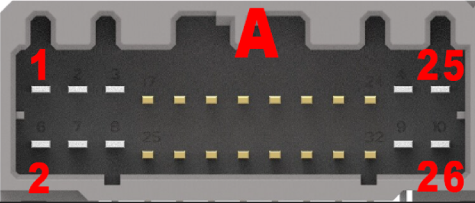
| OBD1 | FUNCTION | TUNERSTUDIO |
|---|---|---|
| A1 | Injector 1 / 4 | Low Side 1 |
| A2 | Ground | |
| A3 | Injector 2 / 3 | Low Side 2 |
| A4 | Ground | |
| A5 | VTEC Solenoid | Low Side 3 |
| A6 | Brake Switch | Digital Input 3 |
| A7 | Fuel Pump Relay | Low Side 4 |
| A8 | FAN Relay | Low Side 5 |
| A9 | Purge Solenoid | Low Side 6 |
| A10 | Alternator Control | Low Side 7 |
| A11 | IACV N | Low Side 12 |
| A12 | CEL | Low Side 9 |
| A13 | IACV P | Low Side 10 |
| A14 | A/C Clutch Relay | Low Side 11 |
| A15 | Free: Injector | Low Side 12 |
| A16 | Distributor ICM | High side 1 |
| A17 | Free: Injector | Low Side 13 |
| A18 | Clutch Switch | Digital Input 4 |
| A20 | A/C Signal | Digital Input 2 |
| A21 | Power Steering Switch | Digital Input 5 |
| A23 / A25 | +12V ignition | |
| A24 / A26 | Ground |
Connector B
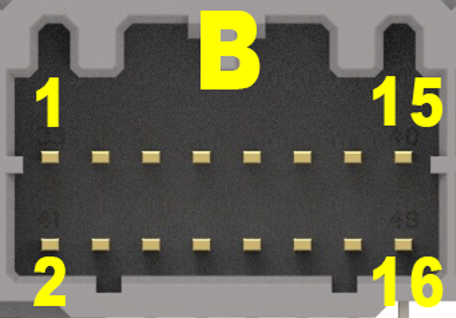
| OBD1 | FUNCTION | TUNERSTUDIO |
|---|---|---|
| B1 | Free | Digital Input 6 |
| B2 | Onboard MAP sensor | Analog Input 5 |
| B3 | Free | Digital Input 7 |
| B4 | Free | Analog Input 7 |
| B5 | Free | Digital Input 8 |
| B6 | Free | Analog Input 8 |
| B7 | +5V for sensors | |
| B8 | Knock Input | Analog Input 9 |
| B9 | +5V for sensors | |
| B10 | Free | Analog Input 10 |
| B11 | +12V for sensors | |
| B12 | Free | Analog Input 11 |
| B13 | Ground for sensors | |
| B14 | Free | Analog Input 12 |
| B15 | Ground for sensors | |
| B16 | Ground for sensors |
Connector C
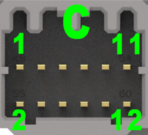
| OBD1 | FUNCTION | TUNERSTUDIO |
|---|---|---|
| C1 | Free | Low side 14 |
| C2 | LSU 4.9 - PIN 5 (IA) | |
| C3 | Tachometer Output | Low side 15 |
| C4 | LSU 4.9 - PIN 6 (NERMEST) | |
| C5 | Coil 1 | High side 1 (E15) |
| C6 | LSU 4.9 - PIN 1 (IP) | |
| C7 | Coil 2 | High side 2 (E14) |
| C8 | LSU 4.9 - PIN 2 (VGND) | |
| C9 | Coil 3 | High side 3 (E13) |
| C10 | LSU 4.9 - PIN 3 (HEATER-) | |
| C11 | Coil 4 | High side 4 (E12) |
| C12 | LSU 4.9 - PIN 4 (HEATER+) |
Connector D
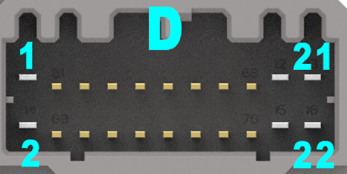
| OBD1 | FUNCTION | TUNERSTUDIO |
|---|---|---|
| D2 | Free - Hall Input | VR/Hall 2 |
| D3 | Vehicle Speed Sensor | Digital Input 1 |
| D7 | TDC | VR/Hall 1 |
| D8 | Tachometer Output | Low Side 15 |
| D9 | Free | Low Side 16 |
| D10 | Free | Low Side 17 |
| D11 | Throttle position sensor | Analog Input 1 |
| D13 | Manifold air pressure sensor | Analog Input 4 |
| D15 | Intake air temperature sensor | Analog Input 3 |
| D16 | Free | Low Side 18 |
| D17 | Coolant temperature sensor | Analog input 2 |
| D19 | MAP ground | |
| D20 | TPS ground | |
| D21 | MAP +5V | |
| D22 | TPS +5V |